
Piezoelectric materials are anisotropic; that is, they do not have the same properties in all axes. It is therefore important to have a form of notation that distinguishes clearly which axis is being referred to in any statement regarding a piezoelectric material.
In Fig. 1 of this article, for example, 3 is the axis of poling (z or thickness), and 1 and 2 (x and y, or width) are the axes perpendicular to the 3 axis.
In OnScale, we default to a Z poling direction, therefore all material properties are entered as if poled in this direction. It is then possible to transpose the matrices to another direction using matr axis.
A piezoelectric material is typically, although not always, electroded along the planes perpendicular to the upper and lower ends of the 3 axis. The directions 4, 5, and 6 refer to rotations about the 1, 2, and 3 axes, respectively. The numbers are often used in subscripts of material constants, in the form xij, where "x" is the constant value, "i" the response, and "j" the applied stimulus.
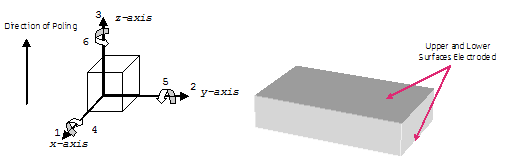
Figure 1
Two common constants define the piezoelectric behaviour of a material under open-circuit (OC) conditions. The first is the piezoelectric stress constant (eij), which is the charge produced per unit stress, expressed in units C/m2. The second is the piezoelectric strain constant (dij). It is equal to the strain produced by a unit electric field and expressed in units m/v or C/N.
| Superscript terminology: | Piezoelectric material properties (mostly used in OnScale): |
| T, constant stress - mechanically free | piezoelectric stress constants [e] units C/m2 |
| S, constant strain - mechanically clamped | piezoelectric strain constants [d] units C/N or m/V |
| E, constant electric field - short circuit | piezoelectric voltage constants [g] units Vm/N or m2/C |
| D, constant electrical displacement - OC | piezoelectric current constants [h] units V/m |
| Piezoelectric constitutive relations: | |||
| E, electric field (V/m) - 3 components (x, y, z) |
D electrical displacement (C/m2), 3 components (x, y, z) |
T stress (N/m2), 6 components (xx, yy, zz, xy, yz, xz) |
S strain, 6 components (xx, yy, zz, xy, yz, xz) |
| [D]=[d][T]+[εT][E] | [D]=[e][S]+[εS][E] | [T]=[cE][S]-[e][E] | [S]= [sE][T]+[d][E] |
| Less Commonly Used: | |||
| [E]=-[h][S]+[εS]-1[D] | [E]=-[g][T]+[εT]-1[D] | [T]= [cD][S]-[h][D] | [S]=[sD][T]+[g][D] |
| Mechanical Properties | ||
| [cE]=[sE]-1 | [sD]=[sE] - [d][g] | [cD]=[cE] + [e][h] |
| Piezoelectric Properties | |||
| [e]= [d] [cE] | [d]=[εT][g] | [g]=[εT]-1[d] | [h]=[g][cD] |
| Dielectric Properties | |||
| [εT]= [εS]+[d][e] | |||
Piezoelectric Material Properties
These constants populate the 3-by-6 piezoelectric matrix. Not all 18 constants, however, have non-zero values and some constants are identical. Most piezoelectric matrices have 5 constants with non-zero values, of which 3 are independent values. The values are entered for each material in the "matr" primary command with the "piez" subcommand. The most common form for the matrix are [e] and [d]. OnScale does not accept [g] or [h] parameters.
Components of [d],[e],[g], and [h] matrices:
| 1 | 2 | 3 | 4 | 5 | 6 | |
| 1(or x) | 0 | 0 | 0 | 0 | 15 or x5 | 0 |
| 2(or y) | 0 | 0 | 0 | 24 or y4 | 0 | 0 |
| 3(or z) | 31 or z1 | 32 or z2 | 33 or z3 | 0 | 0 | 0 |
Usually the components z1=z2 and y4=x5. Piezoelectric properties are therefore usually provided as three numbers, e.g., for [e]:
- ez1 = -9.4
- ez3 = 22.5
- ex5 = 16.0
The z1 component is a negative number for most piezoelectric materials. By default, OnScale accepts the piezoelectric stress constants [e], e.g.:
matr
....
    piez pmt3 1 5 $ex5 2 4 $ex5 3 1 $ez1 3 2 $ez1 3 3 $ez3
or
matr
....
    piez pmt3 strs 1 5 $ex5 2 4 $ex5 3 1 $ez1 3 2 $ez1 3 3 $ez3
OnScale also accepts the dielectric properties in the form of the constant strain[d] matrix. The "matr piez " line, however, must be altered to reflect this:
matr
....
    piez pmt3 strn 1 5 $ex5 2 4 $ex5 3 1 $ez1 3 2 $ez1 3 3 $ez3
Dielectric Material Properties
Dielectric material properties are usually expressed as relative to ε0, 8.85418782 x 10⁻¹² F/m. OnScale accepts permittivity values only when input as absolute permittivity.
- relative permittivity ε r= ε/ ε0
- dielectric constant, under constant stress, εT, dimensionless
- dielectric constant, under constant strain, εS, dimensionless
These constants populate the symmetrical 3-by-3 dielectric matrix; 3 parameters have a non-zero value and 2 have a common value. The values are entered for each material in the "matr" primary command with the "elec" subcommand.
| x | y | z | |
| x | xx | 0 | 0 |
| y | 0 | yy | 0 |
| z | 0 | 0 | zz |
Because usually the components xx=yy, dielectric constants are listed as two numbers, e.g.:
- εSxx = 1306 * ε0
- εSzz = 1200 * ε0
By default, OnScale accepts the dielectric properties for constant strain [εS], e.g.:
matr
....
   elec pmt3 $epxx $epxx $epzz
or
matr
....
   elec pmt3 strn $epxx $epxx $epzz
OnScale also accepts the dielectric properties in the form of the constant stress [εT] matrix. The "matr elec" line, however, must be altered to reflect this:
matr
....
   elec pmt3 strs $epxx $epxx $epzz
Mechanical Properties
Mechanical properties are usually provided under constant electric field (E) but sometimes under constant electric displacement (D). OnScale assumes the constant electric field conditions [cE] and [sE].
- compliance [s] units Pa-1
- stiffness [c] units Pa or N/m2
The use of [s] for compliance and [c] for stiffness are not typographical errors! These constants populate the symmetrical 6-by-6 stiffness or compliance matrix. Of the 21 possible parameters for most common piezoelectric materials, 9 have a non-zero value and 6 independent values. The values are entered for each material in the "matr" primary command with the "type lean" and "matr" subcommands.
Components of [c], or [s] matrices:
| 1 | 2 | 3 | 4 | 5 | 6 | |
| 1 | 11 | 12 | 13 | 0 | 0 | 0 |
| 2 | 21(s) | 22 | 23 | 0 | 0 | 0 |
| 3 | 31(s) | 32(s) | 33 | 0 | 0 | 0 |
| 4 | 0 | 0 | 0 | 44 | 0 | 0 |
| 5 | 0 | 0 | 0 | 0 | 55 | 0 |
| 6 | 0 | 0 | 0 | 0 | 0 | 66 |
Usually the components 11=22, 13=23, and 44=55 and stiffness and compliance properties are given as 6 numbers.
Symmetrical components are always equal, so 21=12, 31=13, and 32=23. These symmetrical values need not be entered into OnScale, e.g., for [c]:
- c11 = 1.14e11
- c12 = 0.757e11
- c13 = 0.724e11
- c33 = 1.11e11
- c44 = 2.63e10
- c66 = 1.92e10
Note: c66 can sometimes be estimated from ((c11-c12)/2)!
By default, OnScale accepts the constant stiffness parameters [c], e.g.:
matr
    type lean
    prop pmt3 $rho
    $c11 $c12 $c13 0.0 0.0 0.0 $c11
    $c13 0.0 0.0 0.0 $c33 0.0 0.0
    0.0 $c44 0.0 0.0 $c44 0.0 $c66
or
matr
    type lean
    prop pmt3 $rho
    stif $c11 $c12 $c13 0.0 0.0 0.0 $c11
         $c13 0.0 0.0 0.0 $c33 0.0 0.0
         0.0 $c44 0.0 0.0 $c44 0.0 $c66
OnScale also accepts material properties in the form of the compliance constants [s]. The "matr/ prop " line, however, must be altered to reflect this:
matr
    type lean
    prop pmt3 $rho
    cmpl $c11 $c12 $c13 0.0 0.0 0.0 $c11
         $c13 0.0 0.0 0.0 $c33 0.0 0.0
         0.0 $c44 0.0 0.0 $c44 0.0 $c66
A piezoelectric material can therefore be defined with the following:
matr
    type lean
    prop pmt3 $rho
    cmpl $c11 $c12 $c13 0.0 0.0 0.0 $c11
         $c13 0.0 0.0 0.0 $c33 0.0 0.0
         0.0 $c44 0.0 0.0 $c44 0.0 $c66
    piez pmt3 1 5 $ex5 2 4 $ex5 3 1 $ez1 3 2 $ez1 3 3 $ez3
    elec pmt3 $epxx $epxx $epzz
where the "$" value indicates that the alphanumeric characters that follow define a variable.
OnScale also includes an attenuation, or loss, component. Most manufacturers list this as a mechanical quality factor, Q. Materials with high Q, such as PZT4, are usually in the 500 to 1000 range; they are generally used in high-power applications such as naval sonar. PZT5H-type materials, used in medical imaging, are often in the 50 to 100 range, and materials such as lead metaniobates, which have low cross-coupling, often have Q factors below 20. A high-Q material continues to "ring" for a long time after being excited, whereas a low-Q material quickly returns to steady state.
OnScale usually uses the "rdmp" subcommand for Rayleigh damping. This combination of mass and stiffness damping represents piezoelectric material damping. The value can be set for both longitudinal and shear damping; most manufacturers, however, give only one Q value. Q is measured and defined at one frequency (e.g., 1MHz) and usually varies linearly with frequency.
rdmp pmt3 $freqdamp q $qdmp $qdmp 1.e6 1.
In the above attenuation statement for the "pmt3" material, the "freqdamp" variable sets the frequency value for Q. This is necessary, as attenuation cannot be matched perfectly at all frequencies and is usually the center frequency of the device. Q indicates that the numbers that follow refer to a quality factor (alternatives are dB and % of critical damping). The next two variables are "qdmp"; they are Q values for longitudinal and shear. The following number is the value at which the Q factor was measured.
The final number is the power to which the Q factor varies with frequency; 1, which is most common, is linear. Fig. 2 in this article shows the requested damping and actual damping, as well the user's attempt to best match the two across a range of frequencies of interest.
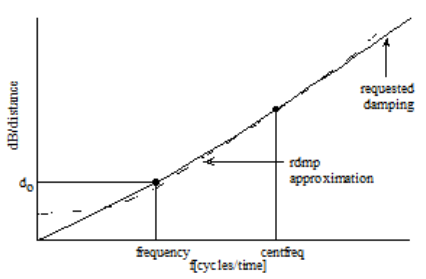
Figure 2.
OnScale follows the below equation across as wide a frequency range as possible. This equation is the most common way of expressing attenuation in the ultrasound community:
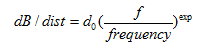
where:
- do = coefficient
- f = all frequencies
- frequency = reference frequency
- exp = exponential value
Manufacturers' Material Properties
Accurate modelling of piezoelectric materials requires 13 independent parameters:
- Density - ρ
- 6 stiffness [c] (or compliance [s]) components: c11, c12, c13, c33, c44, c66
- 3 piezoelectric components ([d] or [e]): ex5, ez1, ez3
- 2 dielectric components ([εT] or [εS]: εxx and εzz
- mechanical Q (dimensionless, entered in one of the "matr/xdmp" commands)
It is important to check which values you are using, e.g. stiffness or compliance, or constant stress or constant strain, and to enter the values correctly.
When you enter a matrix in a given form, OnScale calculates the alternate form and displays those values in the printfile. When you enter the stiffness ([c]) matrix, for example, OnScale calculates the compliance [s] matrix and displays it in the printfile (<jobname>.flxprt).
Although some manufacturers provide all the necessary information (e.g., Ferroperm, http://www.ferroperm-piezo.com/), others do not. In those cases, it is necessary to fill in the blanks" and approximate unknown values by comparison with values for similar, known materials.
Manufacturers' data usually state a margin of error on the values, e.g.:
- stiffness: +/- 5%
- piezoelectric: +/- 10%
- dielectric: +/- 20%
The values vary from manufacturer to manufacturer.
The methodology for entering material properties assumes that the material in question conforms to a tetragonal (4mm) system. This covers the majority of materials used in piezoelectric modelling, including PZT5H. Some materials, such as quartz, may require additional components from the various matrices.
Poling Piezoelectric Materials
Poling in OnScale is done via assigning an orientation to an anisotropic material. For example, if you wish a material to be poled along the positive x-axis, then you have to:
- Define the material via stiffness, piezoelectric and dielectric matrices
- Define a unique axis using the axis command for the required orientation
- Assign the matr prop lean to the direction using matr axis to refer to new axis direction.
This means that materials can be poled in any relative direction (non orthogonal) which allows users to pole angled ceramics and also create curved and radially poled devices.
Users should note that type LEAN materials are by default orientated in the positive-z direction, and therefore, some care must be taken when changing this axis to an arbitrary one. For example, poling a ceramic at 12 degrees off the x-axis:
/* create local axis for poling - remember material is poled in z so have to rotate y
/* 90 degrees to orientate in x then use inclination
symb angle = 12
axis
     form angl
     defn pole cart 0. 0. 0. 0. -90 -$angle
     end
term