
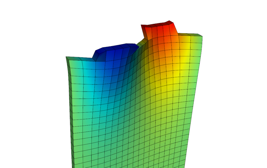
SAW Displacement at Resonance
Model Description
This simple unit cell model of a single port Surface Acoustic Wave (SAW) filter allows rapid simulation of device performance. This allows a very wide range of designs to be explored before moving to more complex full 3D simulations.
The model comprises a pair aluminum electrodes on a piezoelectric substrate. The substrate can either be Lithium Tantalate (LiTaO3) or Lithium Niobate (LiNbO3). The model is set up to simulate a Y-cut, which can be rotated to the desired angle. The base design generates an SH mode at 1.5 GHz using a finger pitch of 1.3 µm.
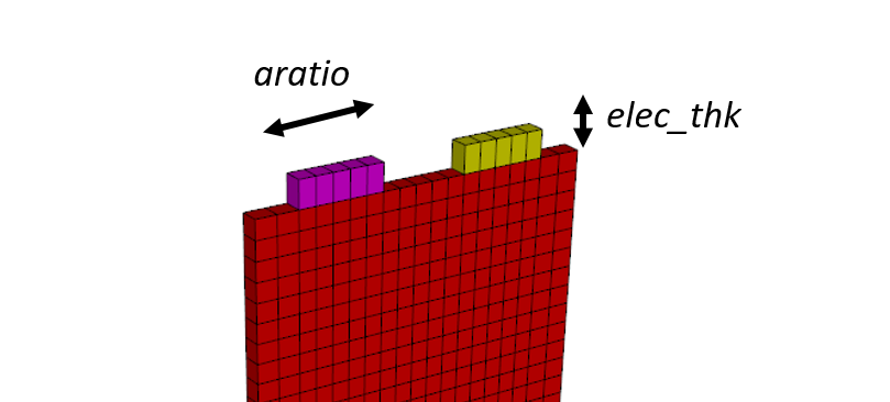
Model Schematic
Design Variables
The base model allows the following design variables to be adjusted. By default electrode thickness and electrode aspect ratio are set as design variables to be swept (indicated by *).
|
Design Variable |
Description |
Default Value |
|---|---|---|
|
elec_thk * |
Thickness of electrode |
200 nm |
|
subs_thk |
Thickness of substrate |
7.5 µm |
|
fin_pitch |
Finger pitch |
1.3 µm |
|
aratio * |
Metalization aspect ratio |
0.5 |
|
nfing |
Number of pairs of fingers in full device |
100 |
|
fin_len |
Length of fingers |
50 µm |
|
piezo_mat |
Piezoelectric material |
lt (LiTaO3) |
|
cut_ang |
Rotated y-cut angle |
42 |
Outputs
A wide range of outputs can be generated, including:
- Electrical impedance / admittance
- S parameters
- Mode Shapes (Harmonic Analysis)
- Energy flow analysis
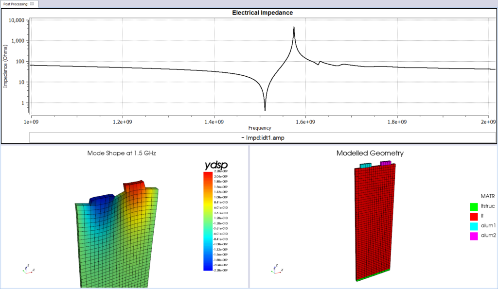
Example Post Processor Outputs
Runtime Statistics
|
Degrees of Freedom |
6222 |
|
Solve Time |
140 s |
|
Core Hours |
0.078 |
|
Memory Usage |
17 MB |
Files
The following input files are required to run this model, click here to download the input files:
Design Studies
The following example design studies were carried out using this model: