The Circuit Tool can be used to create customised circuits out of the following elements:
- Short
- Open Switch
- Resistor
- Inductor
- Capacitor
- Diode
- Transformer
- Co-Axial
- Series RLC
- Parallel
The Circuit Tool can be used within Analyst and Designer and is located in the Tools tab of the Ribbon:
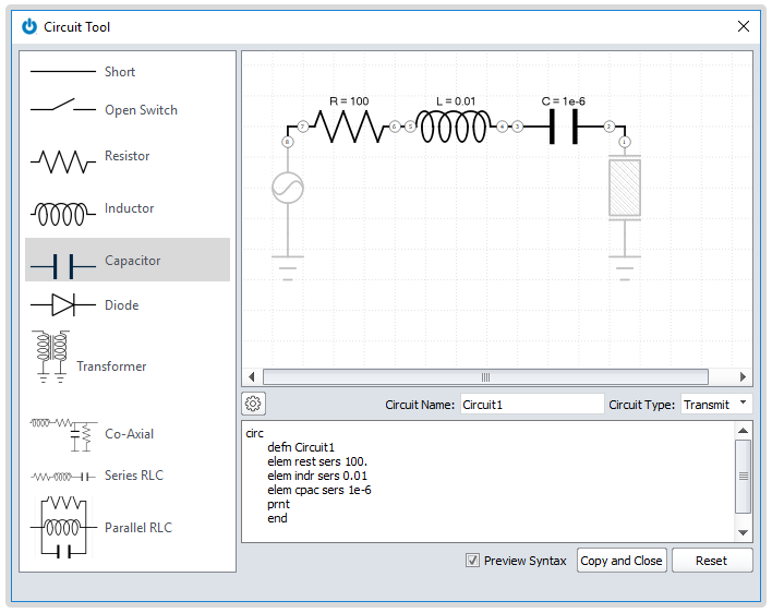
Elements can be added to the circuit by clicking the number located at the chosen position for the element and then selecting the element itself. The user must specify some parameters for each element depending on the type of circuit element that has been chosen. For example, the user would need to specify a resistance value for a resistor or the turns ratio for a transformer.
These parameters can be set by clicking on element and altering the parameters that appear in the bottom left corner of the window. The circuit type can be chosen as either transmit or receive and it can be implemented into a design by either:
- Analyst Mode - Select 'Copy and Close' and then paste using CTRL + V into the flex input file
- Designer Mode - Select 'Insert' and the circuit should appear in the Model Tree
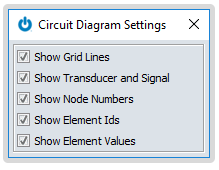
The following settings can be modified by selecting the cog icon and toggling the tick boxes.